Hanze F2A Underbase Grouting GBS (2000)
ABOUT THE HANZE F2A FIELD
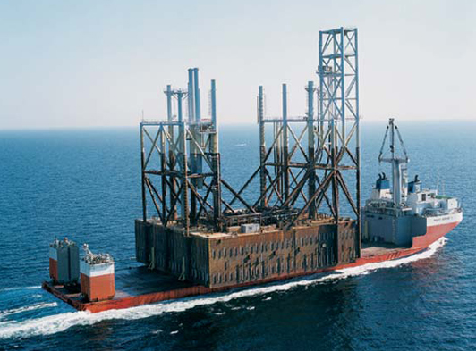
Hanze was the largest field to be developed in the Dutch North Sea. The development is a steel-gravity based production and storage platform. Hanze is located in block F/2 in the Dutch sector, North Sea. The field has reserves exceeding 34 million barrels of oil, as well as 40bcf of associated gas. The field covers 4.5km² between 1,340 and 1,478m below sea level.
GRAVITY BASE STRUCTURE DESCRIPTION
The foundation is of steel construction and gravity base design. It contains 12 central oil storage cells, whilst the cells to the North and South ends of the structure are used for ballast water. The void formed between the underside of the base and the seabed was filled with a sodium silicate/cement grout in order to ensure an even load distribution between the structure and the seabed. The structural integrity of the platform was dependent on the correct placement and retention of good quality grout in the voids beneath the base.
QUALITY CONTROL
During mixing, the slurry density was monitored by densitometers mounted on the mixer units. The slurry density was also monitored at intervals using a pressurised slurry density balance.
One sample was taken during the grouting of each compartment. For each sample the slurry density was measured and recorded three 75 mm grout cubes were manufactured. Each cube was marked to identify the platform, compartment number, time and date of casting and the specific gravity.
The samples were cured underwater at the seabed temperature of 8°C ± 0.5°C until removed for testing. All cubes were tested at age 28 days. Periodic bleed tests were also undertaken using graduated glass measuring cylinders. These were filled with 200ml of grout and a reading of the grout level was taken every 30 minutes for the next four hours. The amount of bleed was calculated as a percentage of the original grout volume, and was generally between 3-6%.
THE MIXING SYSTEM
Compartment grouting was carried out in pairs, with two penetrations in the dividing cell wall to permit grout flow between the first and second compartment of each pair. One primary and one secondary grout line was provided for each pair of compartments, together with two 8” outlet ports located in the outer wall of the second compartment.
Cement was stored in bulk pressurised silos and delivered to a surge tank above the mixer. Water was delivered to the mixer from the vessel firemain pipework and measured into the mixing tank through a mechanical flowmeter. Water entered the mixer through a high pressure jet and cement through a rotary valve at a fixed rate. Sodium Silicate was added via a flow meter through the water jet in a fixed proportion to the water flow rate. The grout was transferred to a ten barrel capacity tank from where it was drawn off by the pump and delivered to the GBS via a flexible hose. The grout was mixed and pumped at a rate of between 40-45m³ per hour. This rate was restricted by the water supply from the vessel.
Grout pumping continued until the theoretical volume required to fill the void had been pumped, and good quality grout flow from the outlets had been confirmed by ROV.
THE ENGINEER’S PERSPECTIVE
Grouting was proceeding well until contingency procedures had to be implemented to successfully fill a number of the compartments.
During filling compartments 101+140, 61+20 and 71+30 it was reported by ROV that the grout was leaking into the adjacent compartments 102, 62 and 72, under the dividing cell walls. These compartments were not designed to be grouted. Together with 112, these were intended for later use during the de-ballasting and removal of the GBS at the end of its life. However, due to this leakage, an additional 50m³ of grout needed to be pumped into each of the leaking pairs to completely fill them and produce good returns from the grout outlet.
No flow was detected by ROV from the grout outlets during filling of compartments 91+130. After approximately 114m³ of grout had been pumped the ROV reported that flow was actually coming from the outlet of 121+160 which had been grouted 5 hours previously. Pumping was then transferred to the secondary grout line, and grouting was successfully completed.
During grouting via the line marked 100+92, the ROV reported that compartments 110+122 were actually being filled. The hoses had been incorrectly labelled. We completed grouting this compartment and moved to fill 100+92 via 110+122’s grout line.