Baobab Gas Pipeline Supports (2009)
ABOUT THE CNR BAOBAB GAS PIPELINE
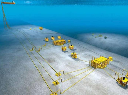
The Baobab field is located in Block CI-40 in the Ivory Coast region. It is approximately 55 miles south west of Abidjan, West Africa, CNR International is responsible for a 6” gas line which runs from an FPSO at Baobab to the main gas export line at Espoir in West Africa, via a 1,250m deep ravine.
FORM WORKS DESCRIPTION
A survey conducted by ROV indicated two spans on the ocean floor. One span was 58m long and 0.6m high on a 13 degree incline, the other was 40m long and 0.3m high on an incline of 22 degrees. Freespans over a certain length require an interim support to be installed to prevent overstressing the pipeline. The most common way of providing such supports is by means of grouted fabric formworks. It was therefore necessary to position fabric formwork structures at 33% and 67% of the spans, which were then filled with grout. In the rectification of the 58m span, a F0-24-1000 fabric form work was used at support 1, and a FO-24-750 fabric formwork at support 2. The 40m span was rectified in the same way, a FO-24-750 fabric form work was positioned at support 1 and a FO-24-750 fabric form work laced at support 2.
QUALITY CONTROL
During mixing, the grout slurry density was monitored by using a pressurised slurry density balance. Two samples were taken during the grouting of each stage: one after approximately 25 percent of the theoretical amount had been pumped, and one after approximately 75 percent towards the end of grouting. For each sample the slurry density was measured and recorded and two 75 mm grout cubes were manufactured. Each cube was marked to identify the formwork, stage, number, time and date of casting and the specific gravity. The samples were cured underwater at ambient temperature until removed for testing. Both cubes from each sample were tested at 28 days. The cubes achieved an average of 75.57 N/mm², which was more than sufficient for the supports installed.
THE MIXING SYSTEM
Grout was stored in bulk 1.5 tonne bags and delivered to a surge tank above the mixer by use of the vessels crane and bag splitter mounted on top of the surge tank. Water was delivered to the mixer from the vessel firemain pipework and measured into the mixing tank through a mechanical flowmeter.
Grout was added to the water through a rotary valve which was controlled by a timer. The grout was mixed by means of a recirculating pump. The grout was then transferred to a 2 m³ capacity holding tank from where it was drawn off by the pump and delivered to the manifold via a flexible hose. Generally the grout was mixed and pumped at a rate of between 5.0 - 8.0 m³ per hour.
THE ENGINEER'S PERSPECTIVE
Once we arrived at the site the clump weight was lifted overboard by crane and hose deployment started. Grout bags were then loaded onto the skid and secured, monkey fists were attached where required and hoses were fastened to the side of the skid so to be clear of the ROV.
The skid was deployed to sea bed and the grout bag released and positioned under the 6” pipeline. The ROV connected the female connector. Poor visibility led to the ROV knocking the skid over with the tether so we flushed the hose with water to inspect for any damage.
The grout bag shifted under the weight of grout so the ROV attempted to reposition the formwork. The first attempt failed and the hose was flushed to stop any grout from curing in the grout line. It was decided to grout the same location this time with a concrete mattress positioned on the upper side of the slope for stability.
The ROV secured the anchoring hooks to the concrete mattress and positioned the grout bag further under the pipeline. Grouting commenced and the grout line was purged with water once the required grout has been pumped until good returns are seen exiting the grout bag. The remaining formworks were also deployed with concrete mattresses for stability.