Fall of Warness (Orkney) Tidal Turbine (2009)
ABOUT THE FALL OF WARNESS
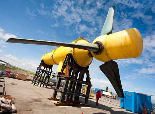
The tidal test site at the Fall of Warness, to the west of the island of Eday, was chosen for its high velocity marine currents which reach almost 7.8 knots at spring tides. The natural channel between Eday and Green Holme islands funnels the huge mass of water that ebbs and flows between the Atlantic Ocean and the North Sea twice a day. The site is managed by the European Marine Energy Centre and provides a test-bed for prototype tidal energy devices.
The water depth for the tidal turbine is approximately 45m below and is a test turbine for Tidal Generation Limited. The biggest issue facing this project was the current in the Fall of Warness. A slack tide which occurred approximately four times a day and lasted between 30 and 75 minutes were the only times rovs were able to operate. This required meticulous planning for each slack tide before work commenced and co-operation between all personnel on board was vital.
FOUNDATION DESCRIPTION
The steel jacket has three pile sleeves in a tripod configuration. The piles are 889mm outside diameter through 1,000mm inside diameter sleeves. The piles had been drilled into nominal 1,000mm ID rock sockets. The connection between the pile, the sleeve and the rock socket was made by injecting a cement grout into the annuli. The structural integrity of the structure was therefore dependent on the placement and retention of sound grout into the pile annuli. The lower end of each sleeve was equipped with a crux type seal to retain the grout.
Each sleeve had a primary and secondary grout line through which grout could be pumped into the annulus. The grout lines had been fabricated with FoundOcean 2” male grout connectors at 3m above the seabed. The grout was to be monitored visually by ROV at the top of the three sleeves.
QUALITY CONTROL
During mixing, the grout slurry density was monitored by densitometers mounted on the mixer units to provide a record of the slurry density. Density was also monitored at intervals using a pressurised slurry density balance.
One sample was taken during the grouting of each sleeve and one sample was taken during grouting of each rock socket. For each sample, four 75 mm grout cubes were made. Each cube was marked to identify the source, time and date of casting and the specific gravity.
The samples were cured underwater at 8oc ± 0.5oc until removed for testing. One cube from each sample was tested at 24hrs and 3 days, and two at 28 days.
THE MIXING SYSTEM
Grout was stored in a bulk pressurised silo and delivered to a surge tank above the mixer. Water was delivered to the mixer from the vessel firemain pipework and measured through a water flow meter. Water was added to the mixer using a calibrated water meter set to a predetermined volume.
Grout was metered into the mixer unit from the surge tank by a time controlled rotary feeder set according to required batch volume and density. The strong vortex action generated in the mixer tank immediately assimilates fresh materials as they are drawn through the mixer housing and shear mixed. The grout was then transferred to a 1,500 litre capacity holding tank from where it was drawn off by the pump and delivered to the structure via a flexible hose.
THE ENGINEER’S PERSPECTIVE
This installation of the turbine foundations was started earlier in the year by an onshore grouting contractor. Towards the end of 2009, Subsea7 and FoundOcean were called in to take over and complete the installation project as the project had over run and was experiencing problems due to the harsh offshore conditions. FoundOcean mobilised their crew of six over Christmas 2009 and had completed the foundation grouting within 18 days of receiving the contract.
The restrictive slack tides and poor weather conditions made it very challenging but collaborative planning meant the project ran smoothly and was finished professionally and swiftly.